NOTE: If you link, please let me know. I would just like to know where this is showing up.
I love college football. A lot. I look forward to the fall to watch my teams compete and (hopefully) win! Since I work for a motion processing company, I though that it would be very interesting to see what forces are imparted to a football once a quarterback decides to throw the ball. So, in January 2011, I took a Friday off from work and decided to make an Inertial Measurement Unit (IMU) enabled football. Deciding I wanted a portable visualization and analysis system, I went on and developed an application on an Android phone (Motorola's Droid / Droid2 platform) that would receive the data from the football via bluetooth and display the data stream and accompanying throw analysis. I also included the ability to replay the throw. Keep in mind that this proved to be a couple 'firsts' for me: First Android application, first time programming in Java and first time using openGL for the visualizations. Unfortunately, it took longer than just a Friday (45 days longer) to make these parts all work together. It was a lot of fun and I hope you enjoy the project details.
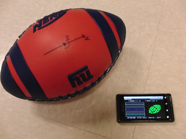
Figure 1 - IMU football and Android application
The system is a fairly straightforward implementation of throw analysis. Since I already have the motion data in their prime forms (no heavy-duty math needed here!), nearly all the calculations were performed with linear algebra techniques. I wanted to have the screen info simple and understandable at a glance.
In this image, you can see the basic elements of the sensor stream visualizations. The accelerometer graph shows the force on the football in 3 dimensions. The gyroscope graph shows the angular velocity on the football in 3 dimensions, and the magnetometer graph shows the footballs movement through the earth's mag field in 3 dimensions (You can use this data to derive the heading of the ball, but I need more time to write the math to perform this). On the right side is a wire frame graphic of the football. This will show the orientation and motion of the football as received by the Android phone. The text on the top of the screen are throw and catch indicators. The text on the bottom show total samples received, and the current angular velocity of the football.
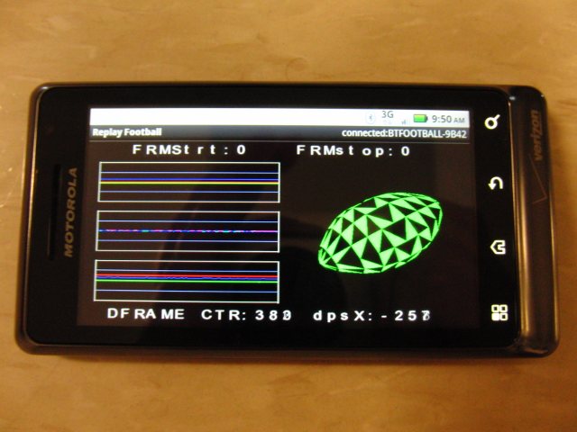
Figure 2 - Data collection mode
Once a throw/catch combo has been detected, a tap motion on the screen of the algorithm will activate the Replay mode. This will playback your throw, showing the forces, rotations and graphic showing football orientation from time of release to time of catch. Also, this is played back slower -- at 75% speed, to give the user a chance to see the details of the throw. The text on the top of the screen show release velocity(RVel) of the throw and the time in flight(FltDur). The text on the bottom shows precession(Precess) of the football and the accompanying angular spiral velocity(RPM). The minus sign indicates a clockwise, or counterclockwise spiral rotation.
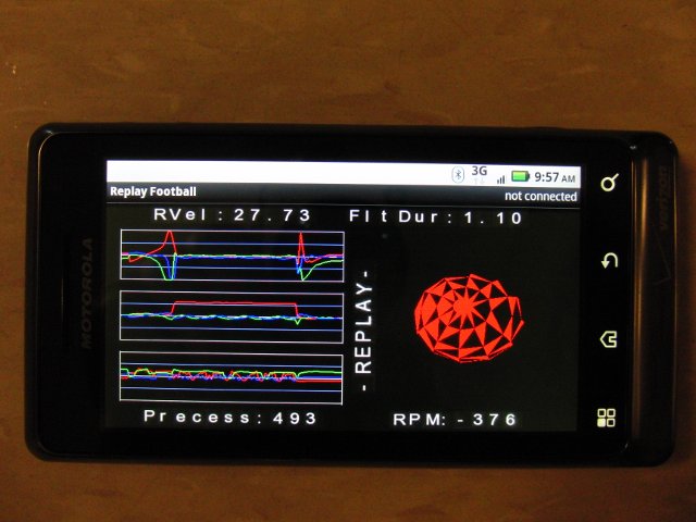
Figure 3 - Replay mode
A long-press motion on the screen of the Droid will reset the data collection, ready for another throw to analyze.
The application can capture up to 15 seconds of continuous data before the oldest point is overwritten. To date, the world record for longest hang time is 8 seconds (with an American football), so this should give plenty of buffer for any level-playing field use.
Video 1 - Perfect Spiral training in action!
Also, for fun, the football has 32 LED's bordering the perimeter. The basic concept(explained in detail below), is that the faster you spin it, the more red the LED's become. The sequence is green->orange->red for slow->medium->fast spirals. Note: It was difficult to capture the illumination of the LED's. Shooting the video during the day, the illumination sequence was not obvious. A night time shot was the only way to get the LED's to show up on the video. In person, the LED's are bright enough to be seen inside of a gym or outdoors in the evening.
Video 2 - Football illumination (sorry for the poor video)
| Quantity | Type | Cost |
|---|---|---|
| 1 | Nerf Football | $15 |
| 1 | Sensor board - Accel, Gyro, Compass, Micro controller, charger | $225 |
| 1 | Bluetooth transmitter | $65 |
| 1 | LiPo Battery 1200mAH | $9 |
| 32 | Red and Green Bi-color LEDs | $5 |
| 2ft/10ft | Velcro / connection wire | $10 |
| 1 | 3M Contact Adhesive | $14 |
| 4 | N-channel FETs + Mounting PCBs | $10 |
| 16 | PNP Transistors + Mounting PCBs | $15 |
The first step was to find a Nerf football. I wanted one of the older models that would glow in the dark when a light stick into the middle of the ball. Seeing that the aforementioned model was difficult to source, I decided to go with the regular rubber coated foam football. Using a razorblade, I breeched the outer rubber skin by carefully cutting around the oblong edge of the football. Then using a wet bread knife, I bifurcated the football into two halves. Then, using a Router, its high speed bit was able to cut rounded notches in the rubber edge to hold bi-color LEDs.
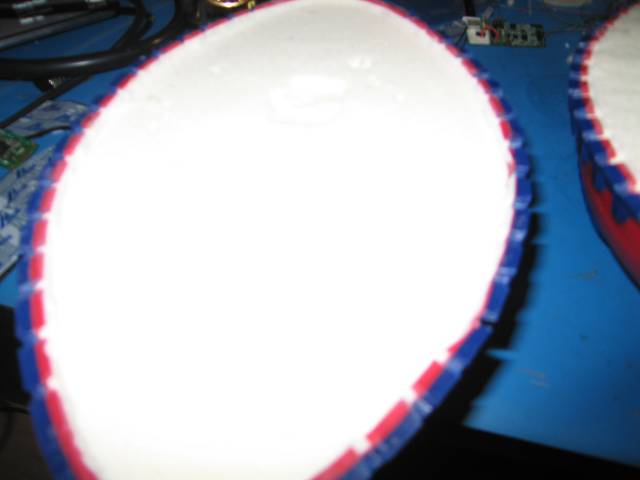
Figure 4 - Football cut into two pieces
Since I needed to re-assemble the halves, so I decided to use velcro. The velcro was cut to fit inside the rubber portion of the football, on top of the foam. on one half of the football, I removed 1/4" of foam to accommodate the thickness of the velcro. This was accomplished using the Router and setting it to the specified depth. Also, I took this opportunity to carve out a space for the battery, sensor pack and the associated power electronics to drive the 32 LEDs.
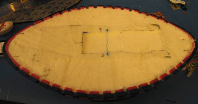
Figure 5 - Accommodation for internal components

Figure 6 - Fitting the Velcro
Most of the assembly time went into handling the LEDs. Each had to be hand soldered and heat-shrink tubing applied to solder joints to prevent the wires from breaking while playing with the football. This took approx 8 hours.
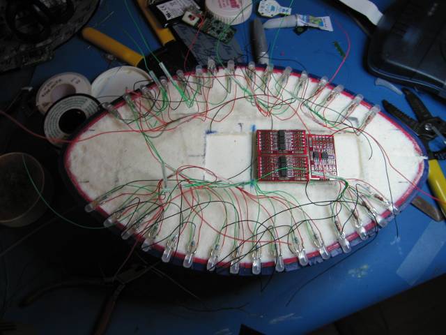
Figure 7 - Spider web of wires and LEDs
Using a little 3M spray contact cement, the LEDs were held in place and the remaining wires were connected to their appropriate locations. Take note that the micro controller used in the sensor pack is an xMEGA192A2. This can only sink/source approx 20mA per GPIO, with a max micro controller current rating of 200mA. This limitation forced me to use FETs to handle the driving of the LEDs on the perimeter of the football.
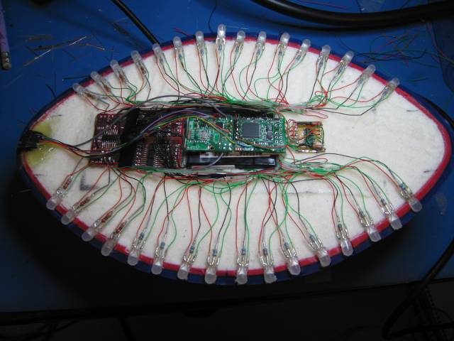
Figure 8 - All wired together
To limit the necessity of opening the football for programming, I decided to have a connector toward the end of the football to handle charging and programming. Also, it was a convenient location for the power switch.
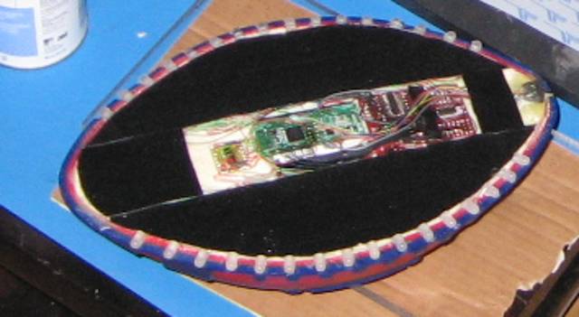
Figure 9 - Velcro installed
After all the wires were soldered to their appropriate locations and the LEDs were aligned within their slots, the 3M contact adhesive was used to bond the velcro to the ball foam. This provided a surprisingly strong bond and would tear a foam layer before the adhesive would release.
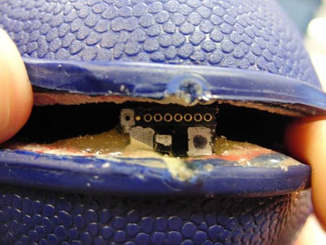
Figure 10 - End connector
After the contact adhesive got a chance to cure, the football was assembled by aligning the two halves and pressing together. The velcro surface area was more than adequate for keeping the halves together. The football halves did not slip against each other when the assembled football was thrown.Even though a gap was still present, this did not adversely affect the flight of the football. The velcro was dense enough to prevent airflow through the center of the ball.
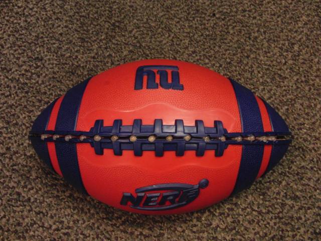
Figure 11 - Assembled football
When thrown, the LEDs will light up sequentially in rapid succession. Combining this with the spiraling nature of the football, the illumination pattern also takes on a spiral shape.
Before the android application was written, the purpose of the LED's on the outside of the football are to indicate the speed of the football spiral. When the football is thrown with an angular rate of 100 RPM, the Green LEDs will illuminate. If you can spin the football faster, then the LEDs will illuminate orange at 400RPM. And if you are a superstar, the LEDs will illuminate red if thrown with an angular velocity above 700RPM. At stationary, and movements below 100RPM, the LEDs remain off. Keep in mind that a professional quarterback can throw an average spiral speed of 600RPM.
Having LEDs on the outside of the football is only a secondary interest when the football is being used. The primary interest is the data being transmitted from the football via the Bluetooth link. Accel, Gyro and Compass data accurately describe the motion of the football from the time it leaves the throwers hands until it reaches the receivers grasp.
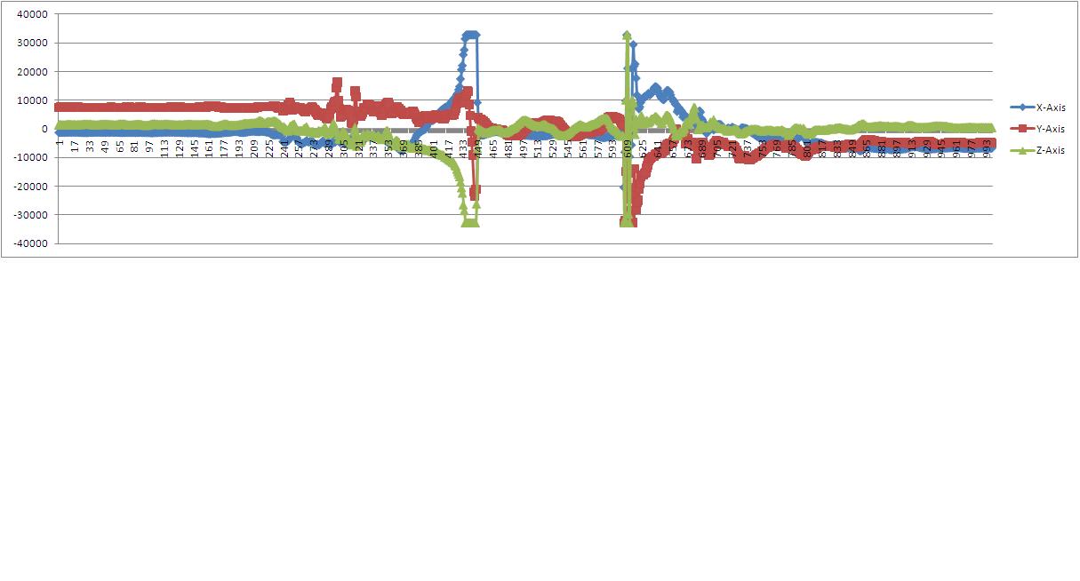
Figure 12 - Accelerometer data

Figure 13 - Gyro data
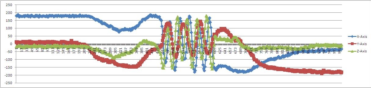
Figure 14 - Compass(magnetometer) data
From this simple collection of raw sensor data, the quality of throw is clearly shown. This particular data set shows an off-center throw(colloquially known as a 'throwing a duck'). Notice in the accelerometer data, the left peak is the release from the throwers hands, and the right peak is the catch event by the receiver. Also, it should be noted that on the gyro, the sensor axes perpendicular to the direction of travel are recording significant movement. Perfect spirals will register nearly all rotation on the prime rotational axis, X-Axis in this case. The Y and Z axes should show only minor rotational movement.
Using this developed Android application, it is clear that a singular throw could be analyzed for its quality, with the intent of being a valuable training tool.
Please note that I don't necessarily support the NY Giants. It is the football which was available at the time. :-)
Also, I want to give a shout out to David Floco(who was humble enough to give a poor throw) and Dan Baarts for helping with the video, Sean Davis who helped with the wireframe football, and Pat Hickey for helping with the Sensor Fusion engine.
Go Fresno State Bulldogs and Nebraska Cornhuskers!
Last updated March 29th, 2011 - Copyright Enfinicorp.
Page maintained by: benkokes@hotmail.com